Discover the industry's first TÜV-certified GoogleTest & Agentic AI solution for C/C++ testing! Get the Details »

Explore the Chapters
The Radio Technical Committee for Aeronautics (RTCA) DO-178C is a functional safety standard that provides guidance and considerations for the production of software for airborne systems and equipment. The aim is to ensure that the system performs its intended function with a level of confidence in safety that complies with airworthiness requirements. If an aircraft is to fly over commercial U.S. airspace, compliance with the standard is required.
The sections that make up the DO-178C standard
DO-178C provides the following guidance:
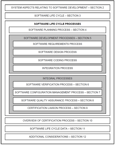
DO-178C covers the full engineering life cycle. From planning, development, verification, quality assurance, liaison, and certification. It is subdivided into 12 sections. Section 1, not shown expresses the purpose, scope, and how to use the document.
RTCA was founded back in 1935. They are an independent standards development organization and serve as the basis for government certification of equipment used by the tens of thousands of aircraft flying daily through the world’s airspace.
RTCA is a private, not-for-profit corporation, which works closely with the Federal Aviation Administration (FAA) and industry experts from the U.S. and around the world, such as the European Organization for Civil Aviation Equipment (EUROCAE) working group to help develop this comprehensive, contemporary aviation standard. The EUROCAE is a non-profit organization with the objective of developing standards for European civil aviation.

The original DO-178 standard was released back in 1982. However, it was not considered useful. As a result, the DO-178A revision followed, published in 1985. This revision focused more on modern software engineering principles and verification practices. It introduced a correlation between critical failure conditions with level numbers 1, 2, and 3. Level 1, which you may know better as Development Assurance Level (DAL) was the strictest.
In December 1992, revision DO-178B was released, which shifted from a "how to" type of document to a "what to do" type of document. A big focus was put on objectives that your software process needs to satisfy in order to reach compliance and ultimately certification.
Another noticeable change was to the number of possible critical failure conditions defined in DAL.They grew to five software levels and changed from numbers to letters A through E. Level A was the most stringent and Level E meant no safety requirement. Also, testing your requirements was strongly emphasized. It advised not to look at the code to create test cases, but to look at your requirements. It was backed by structural code coverage to ensure that you have covered everything.
DO-178B also incorporated bidirectional traceability between systems, high- and low-level requirements, including test cases, and down to the code to show that all the requirements have been implemented. The idea of having tools qualified for use was introduced.
Today, we’re at revision C. Released in January 2012, DO-178C removed imprecise wording found in DO-178B for clarification. It also became a joint effort between RTCA and EUROCAE. But the major difference between DO-178B and DO-178C is the adoption of a modular approach to supplemental guidance documents. You now have supplemental standards, including the following.
This guide provides a condensed overview of each of the DO-178C sections, highlighting the key takeaways.
Section 2 discusses the system life cycle processes, the artifacts produced, how they flow down into the software life cycle and the information flow between these processes. A big part of this is requirements analysis, where the software system requirements are initially developed from the system operational requirements or customer requirements, and how these artifacts flow into the software life cycle.
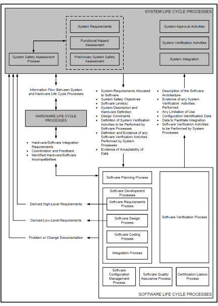
Information flow between system and software life cycle processes. The Guideline Enforcement Plan demonstrates how each MISRA guideline is verified.
In the software life cycle, requirements decomposition continues, software verification takes place, and ultimately certification.
Though DO-178C captures the flow between system and software life cycles in the diagram above, the topic is well defined in the SAE ARP4754A standard, Guidelines for Development of Civil Aircraft and Systems.
Section 2 discusses the following topics:
One other important part of section 2 is determining the software level classification or DAL. Catastrophic results equate to failure of flight control software where an aircraft would go down and many lives would be lost. This would be classified as software level A.

Hazardous is a step down, so serious or fatal injury to a relatively small number of the occupants other than the flight crew would be software level B. The classification continues to go down to software level E where there’s no safety concern if failure were to occur.
Another perspective or side of this classification is quality assurance. With each increased level from level E to level A, there’s an increased number of objectives that need to be met. For example, there’s an increase in traceability between artifacts produced during product development. Also, there’s an increase in software testing. The software may need to satisfy assembly or object code coverage instead of just statement, branch, and MC/DC coverage.
To share a best practice, if your software is classified at level B or lower, you may want to try to achieve some or all of the next higher software level objectives. The additional effort between some of the development assurance levels may not be too substantial and the benefits could very well pay off if customer requirements become more stringent.
Below is the well-known V-model. The right side captures the system and software design phases while the left side captures the verification phases. Standard ARP4754 is your go-to document on the development of aircraft systems considering the overall aircraft operating environment and functions. This includes validation of requirements and verification of the design implementation for certification and product assurance.
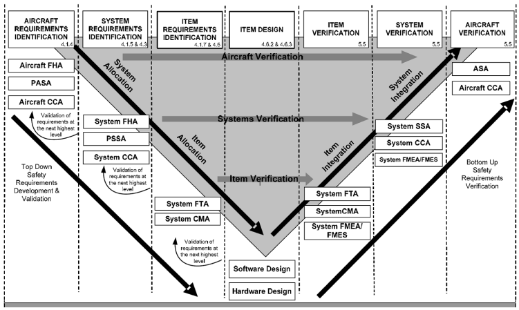
ARP4754A V-model development process
Section 3 discusses the aspects of the software life cycle process. The well-known sequence through the SDLC is requirements management, design, coding, and integration. DO-178C does not recommend a development process to use. It’s left up to organizations to make that decision based on their own experience and factors like current technology, such as Agile, DevSecOps, CI/CD, or customer requirements. Whatever process you choose, the standard’s objectives that must be met are not obstructed by the process.
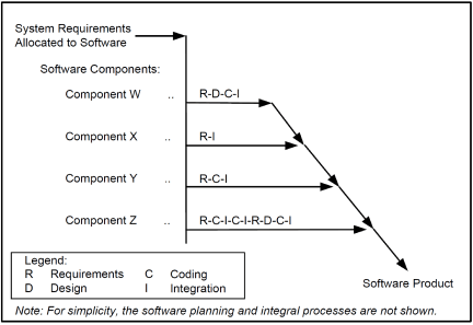
DO-178C example of a software project using development sequences
DO-178C software life cycle processes include the following:
Section 4 discusses the objectives and activities of the software planning process. The objectives are clearly defined and captured in Table A-1 of the standard. There are seven objectives that must be satisfied based on the software level (A-D). These objectives include defining the following:
There are also many considerations to the software planning process, like the intent to use previously developed software or commercial off the shelf software (COTS), tool qualification, and many more described in section 12.
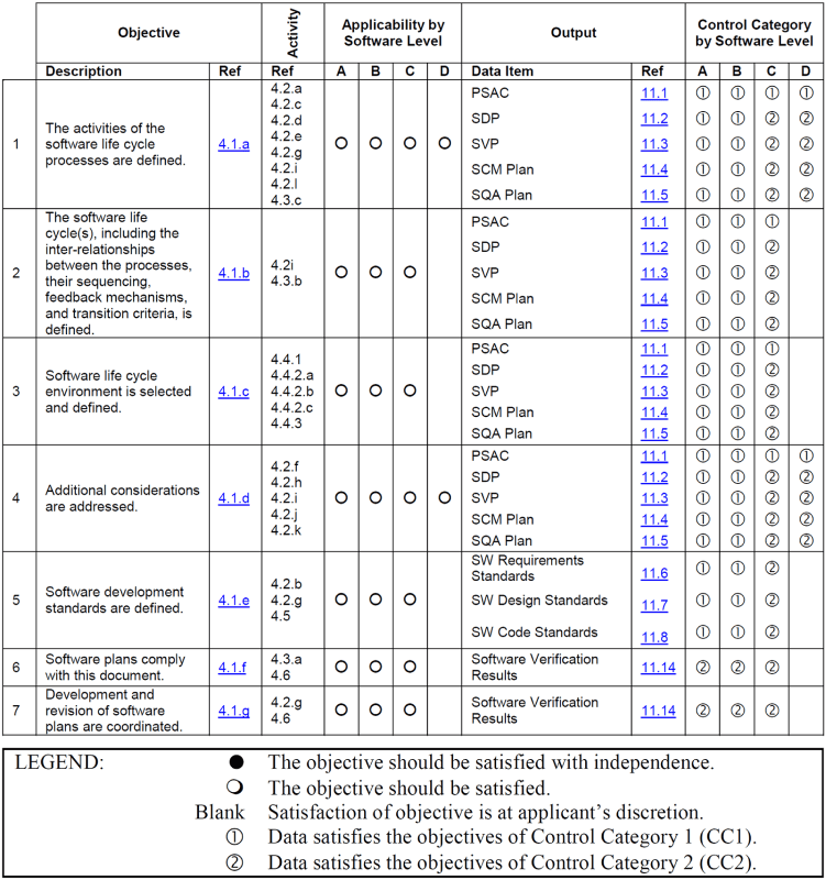
Table A-1 Software planning process
The software development process is applied as defined by the software planning process and the software development plan. Whether teams or organizations choose a software development methodology like DevOps, Spiral, Waterfall, or another, the following four listed processes must be performed.
The software requirements process begins by gathering all requirements from the stakeholder, regulatory bodies, standards, and more. These requirements are organized into domains such as hardware, software, mechanical, chemical, electrical, and so on, and then become your system-level requirements.
High-level requirements are derived from top-level system requirements. They decompose a system requirement into various high-level functional and nonfunctional requirements. This phase of the requirements decomposition helps in the architectural design of the system under development.
High-level requirements clarify and help define expected behavior as well as safety tolerances, security expectations, reliability, performance, portability, availability, scalability, and more. Each high-level requirement links up to the system requirement that it satisfies. In addition, high-level test cases are created and linked to each high- level requirement for the purpose of its verification and validation. This is part of the software design process, as each high-level requirement is further decomposed into low-level requirements.
Low-level requirements are software requirements derived from high-level requirements. They further decompose and refine the specifications of the software’s behavior and quality of service. They drill down to another level of abstraction and map it to individual software units. The coding process begins as code units are written to facilitate the software’s detailed design and implementation. The inputs to the coding process are the low-level requirements and software architecture from the software design process, the software development plan, and the software code standards.
After the coding process is complete, the integration process consists of the following:

Coding defects need to be identified and fixed. Inadequate or incorrect inputs detected during the integration process should be provided to the following software processes as feedback for clarification or correction:
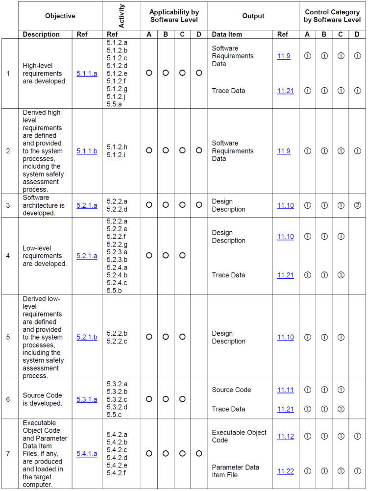
DO-178C Table A-2 Software development process
Bidirectional traceability that is established from each low-level requirement up to its high-level requirement and down to the low-level tests or unit test cases that verify and validate it helps in this endeavor.

Traceability is crucial to DO-178C. The depth of traceability varies based on the software level. Looking at the traceability that’s required for DO-178C level D, organizations need not care about how the software has been developed, and as such, there’s no need to have any traceability down to low-level requirements, the source code, or software architecture. Teams just need to trace from the system software requirements to the high-level requirements and then to the test cases, test procedures, and test results.

For levels B and C, how the source code has been developed becomes important. Teams need to expand traceability by adding bidirectional links from the high-level requirements to the low-level requirements and to the source code.

For level A projects, the requirements are to expand the traceability not just down to the source code, but to the assembly/object code. This is because compilers are known to expand and translate higher level languages to assembly code that does not map back to the originating code.
Parasoft has an assembly code coverage solution called ASMTools that automates code coverage at the assembly language level. Automating this effort alleviates much labor if code coverage at the assembly level is required.
For requirements traceability, Parasoft automates linking between requirements, test cases, and down to the source file, if required. Integrations with ALM tools like Jama, Codebeamer, and Polarion exist to help achieve this bidirectional traceability and building a traceability matrix for verification requirements.
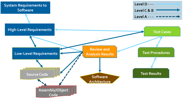
Requirements traceability through DO-178C software levels (D-A)
The purpose of the software verification process is to detect, report, and remove the errors that may have been introduced during the software development process. The standard uses the term "verification" instead of "test" because testing alone cannot show the absence of errors. Verification is a combination of reviews, analysis, tests cases, and test procedures.
Tests provide internal consistency and completeness of the requirements, while test executions provide a demonstration of compliance with requirements.
DO-178C software verification process enables the following:
Software testing demonstrates or "validates" that the software satisfies its requirements and reveals with a high degree of confidence that errors that could lead to unacceptable failure conditions, as determined by the system safety and security assessment process, have been removed. The following diagram shows software testing activities with subsections.

To further detail each testing activity, the standard provides a set of tables with well- defined objectives and outputs or artifacts needed to demonstrate compliance. These objectives are achieved by way of software testing and may include the following:
Integrating hardware and software is crucial to ensuring safety, security, and reliability.
Be aware that all of these testing methods are automated by Parasoft’s tool suite. You can get a glimpse of our C/C++ solution by taking a tour of Parasoft C/C++test.
The following tables list the set of objectives and expected outputs based on each software design assurance level in order to ensure airworthiness.
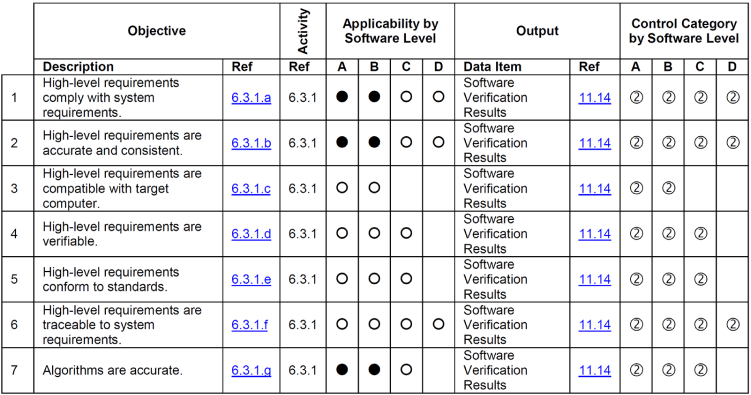
DO-178C Table A-4 Verification of outputs of software design process
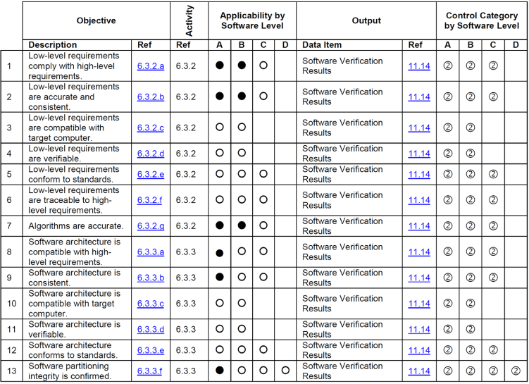
DO-178C Table A-4 Verification of outputs of software design process
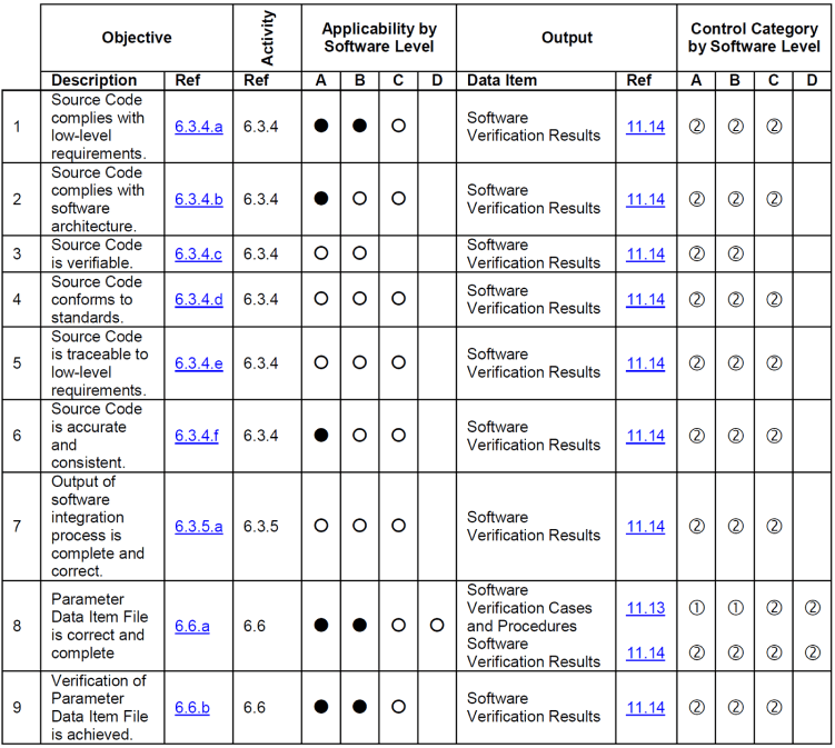
DO-178C Table A-5 Verification of outputs of software coding and integration processes
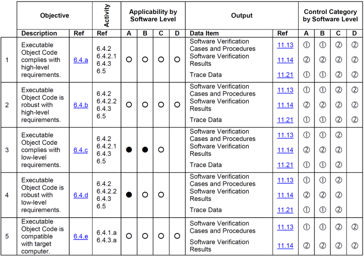
DO-178C Table A-6 Testing of outputs of integration process
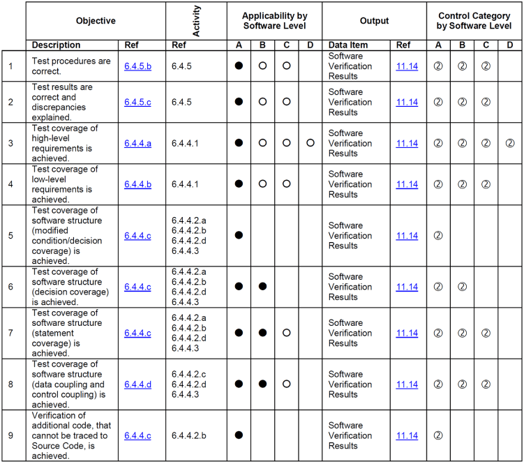
DO-178C Table A-7 Verification of process results
Section 7 discusses the objectives and activities of the software configuration management process. You need to be able to define and control configurations of the software throughout the software life cycle. Organizations or teams need to have source baselines, versioning, change control, change review, protection against unauthorized changes, problem reporting, and much more.
These are the software configuration management process activities:
These activities are further detailed as objectives and their output. The objectives include being able to control item characteristic changes, record and report change control processing, and implementation status.
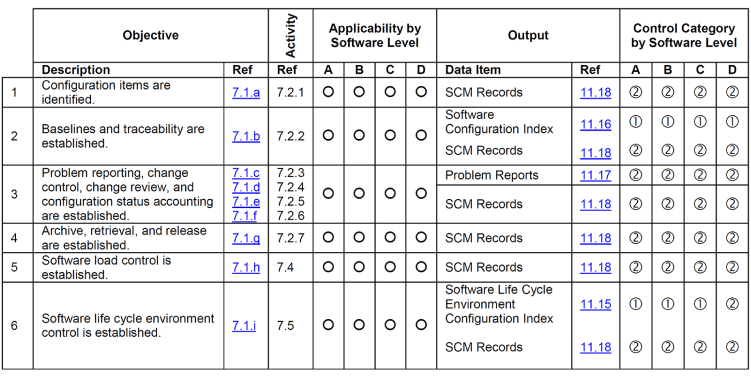
DO-178C Table A-8 Software configuration management process
In Table A-8, notice the "Control Category by Software Level" column. DO-178C specifies which items must be treated as Control Category 1 or 2 based on the project’s DAL. Items treated as Control Category 1 (CC1) must undergo full problem reporting processes, formal change review, and release processes. CC2 items do not need to undergo these more formal processes, but they must still comply with configuration identification and traceability needs, be protected against unauthorized changes, and satisfy applicable data retention requirements. The map between CC1 and CC2 data is found in the following table.
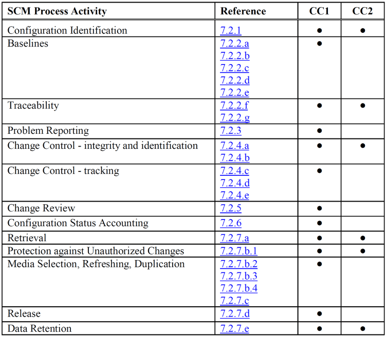
DO-178C SCM process activities associated with CC1 and CC2 data
The SQA process is captured in the Software Quality Assurance Plan, which is built during the software planning process. Outputs of the SQA process activities need to be recorded, evaluated, and tracked. Audits need to be performed and any deviations from the standards be resolved. The process entails providing assurance that:
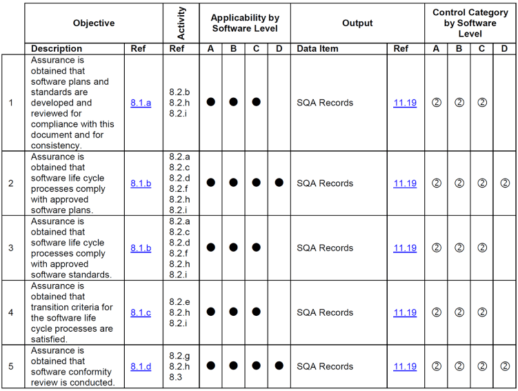
DO-178C Table A-9 Software Quality Assurance Process
Section 9 discusses the certification liaison process and its objectives, which include the following:
Your organization will need to produce the Plan for Software Aspects of Certification (PSAC), which will contain the certification liaison process. The PSAC will include plans on resolving issues identified by the certification liaison and obtaining agreement on the plan. The table below lists the set of objectives and expected output artifacts.
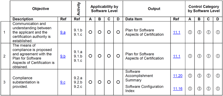
DO-178C Table A-10 Certification liaison process
Best practices for obtaining certification boil down to closely working with your certification liaison, who may be better known as your Designated Engineering Representative (DER), to evaluate for compliance, act on your behalf toward approval, and recommend that the FAA approve your certification.
Section 10 is for informational purposes only regarding the certification process.
It mentions the types of systems and equipment to which certification applies. It specifies that certification authorities do not certify software as a unique stand-alone product. It must be part of the airborne system or equipment.
Approval also depends upon a successful demonstration or review of the products produced.
Section 11 discusses artifacts like the data and documentation produced during the software life cycle. The data needs to be unambiguous, complete, verifiable, consistent, modifiable, and traceable. It also must be in various forms like electronic and printed.Parasoft’s automated report generation and analytics web dashboard provide much of the information needed within various artifacts and documents.
The artifacts to be produced during the software life cycle include the source code, object code, test cases, results, problem reports, and, of course, the plans. Here’s the full list.
Section 12 provides additional guidance and consideration on topics that can have an impact on objectives and activities in the software life cycle. For example, the use of or modifications to previously developed software. Section 12 provides additional clarification and activities to perform that help ensure safety and recertification. Here are just some other considerations include:
Changes to the development environment such as processor, programming language, auto code generator, development tools, and the like.
Upgrading a development baseline.
Use of already certified software on an alternate type of aircraft
Use of certified software where there’s a change in the compiler or processor.
Based on the consideration, section 12 provides additional objectives in software configuration management, software quality assurance, development tool qualification, and more.
Section 12 covers the importance of "Tool Qualification" and determining if its needed. This is because if a tool is used that eliminates, reduces, or automates processes, teams need to take into consideration whether the tool might introduce errors into the life cycle.
The following criteria should be used to determine the impact of the tool:
Criteria 1
A tool whose output is part of the airborne software and thus could insert an error.
Criteria 2
A tool that automates verification processes and thus could fail to detect an error, and whose output is used to justify the elimination or reduction of:
Criteria 3
A tool that, within the scope of its intended use, could fail to detect an error.
There are five levels of tool qualification, TQL-1 through TQL-5, that are determined by the tool use and its potential impact on the software life cycle. TQL-1 is the most rigorous level. The tool qualification level needs to be coordinated with the certification authority.
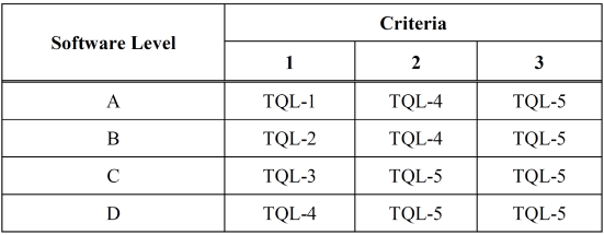
DO-178C Tool qualification level determination

The objectives, activities, guidance, and life cycle data required for each tool qualification level are described in DO-330, "Software Tool Qualification Considerations."
Parasoft supports DO-178C and DO-330 conformant tool qualification processes with an automated tool qualification kit. The Tool Qualification Kit automates the process of creating the supporting documentation required in using C/ C++test for static analysis, unit testing, and coverage requirements.
Parasoft’s Tool Qualification Kit reduces the time taken to perform the tool qualification and the potential for human error by leveraging automation to guide users through the following workflow:
